
Now, since we are controlling a single DC Motor, we need to use a single channel of the L298N. Then, make the GND terminals of Raspberry Pi and L298N Motor Driver Module common (connect them together). First connect 12V Power Supply to L298N Motor Driver Module. The design of the Raspberry Pi L298N Motor Driver Interface Circuit is very simple.

The pin diagram of the L298N Motor Driver IC is shown in the image below. The L298N Motor Driver Module is based on the powerful L298N Motor Driver IC. It became so popular that the module is now available at a very low cost. In recent times, L298N Motor Driver Module has become the favorite choice of hobbyists and makers when it comes to DC Motor Control. So, first, let me take you through a simple introduction to L298N Motor Driver Module. How different will it be for controlling a DC Motor using Raspberry Pi with L293D and L298N? Well, there won’t be much of a difference as essentially both these modules serve the same purpose.īut it is always nice to learn about something new and implement it into a project. If you remember, I have already made a project on CONTROLLING A DC MOTOR WITH RASPBERRY PI using L293D Motor Driver. When I say control a DC Motor, I mean you can start a motor, stop it, make it rotate in forward direction, backward directions, increase the speed of rotation and also decrease the speed.įor this, I’ll be using the L298N Motor Driver Module. Interfacing L298N Motor Driver Module with Raspberry Pi will allow us to control a DC Motor (in fact, you can control two DC Motors).
#L298n motor driver prce full#
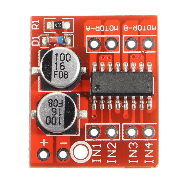
This module is based on L298N,high voltage,high current dual full bridge driver which can be used to drive a DC motor and stepper motor, relay coil inductive load using standard logic level signal control having two enable control end allow or prohibit the work has a logic device power supply input terminal, in the case regardless of the input signal affect the internal logic circuit portion to operate at a low voltage can be an external sense resistor, the amount of change in feedback to the control circuit. This module can drive either 2 DC motors or 1 Stepper motor at a time.


 0 kommentar(er)
